What Is Industrial Computer Vision?
Industrial computer vision is the use of cameras and image processing to make automated decisions on a production line. A camera captures an image, software analyses it against defined criteria, and the result triggers an action — accept, reject, adjust, or guide a robot.
It differs from consumer vision in one important way: the environment is controlled. Lighting, camera position, part orientation and background are all fixed by design. That control is what makes reliability above 99% achievable, and it is why so much of the engineering effort goes into the physical setup rather than the algorithm.
The Four Core Applications
Almost every industrial deployment falls into one of four categories.
1. Inspection
Detecting defects: scratches, cracks, contamination, missing components, incorrect assembly, print and label errors. This is the highest-volume use and usually the easiest to justify financially, because the cost of a defect escaping is known.
2. Measurement (metrology)
Non-contact dimensional checks — diameters, gaps, angles, edge positions. Vision measures faster than a probe and does not touch the part, which matters for soft, hot or delicate items.
3. Guidance
Telling a robot where a part actually is, rather than assuming it is where the fixture intended. This removes the need for expensive precision fixturing and allows robots to pick from bins, conveyors and loosely presented trays.
4. Identification and tracking
Reading barcodes, data matrix codes, printed text and serial numbers to maintain traceability through the process.
How a Vision System Actually Works
A production vision pipeline has five stages:
- Trigger. A sensor or PLC signal fires the capture at the exact moment the part is in position.
- Acquisition. The camera captures under controlled lighting, with exposure short enough to freeze motion.
- Pre-processing. Correcting lens distortion, normalising contrast, isolating the region of interest.
- Analysis. Either classical algorithms (edge detection, template matching, blob analysis) or a trained neural network — often both.
- Decision and output. A pass/fail signal or coordinate set returned to the PLC or robot controller, typically within milliseconds.
Classical algorithms or machine learning?
Classical methods are the right choice when the defect is geometrically well defined: a measurement, a present/absent check, a code to read. They are fast, deterministic and easy to validate.
Machine learning earns its place when the defect is visually obvious to a person but hard to describe in rules — surface texture flaws, casting irregularities, cosmetic finish. The trade-off is that it needs labelled examples, including examples of the defect, which are often the hardest images to collect.
Lighting and Optics: Where Projects Succeed or Fail
More vision projects fail because of lighting than because of software. If the defect is not clearly visible in the raw image, no algorithm will find it reliably.
- Backlighting produces high-contrast silhouettes — ideal for dimensional measurement and presence checks.
- Diffuse dome lighting removes specular highlights from curved or shiny surfaces.
- Low-angle (dark field) lighting makes scratches and engraved marks stand out against an otherwise uniform surface.
- Coaxial lighting gives even illumination on flat reflective parts such as machined faces and PCBs.
Practical test: if a person cannot reliably spot the defect in a still frame from your setup, the lighting is wrong. Fix the optics before touching the algorithm.
Ambient light is the other common failure. A system validated during a night shift can behave differently in daylight. Enclosures and shrouds are cheap insurance.
Deployment Considerations
Define the defect before buying hardware
“Detect defects” is not a specification. You need the smallest defect size that must be caught, the acceptable false-reject rate, and the acceptable escape rate. These three numbers determine camera resolution, optics and cycle time.
Cycle time is a hard constraint
The vision system must complete capture and analysis within the line's takt time, including the worst case rather than the average. Build in margin.
Collect defect images early
For any machine-learning component, images of real defects are the scarce resource. Start collecting them as soon as the project is approved — waiting until the model is being trained can add months.
Plan for drift
Lenses accumulate dust, lights dim, mounts shift with vibration and suppliers change material finish. A production system needs periodic verification against known-good and known-bad reference parts, plus a clear escalation path when it starts rejecting more than usual.
How M PRO9 Approaches Vision Projects
Our sequence is deliberately physical-first:
- Feasibility imaging. Before any quotation, we capture sample parts under several lighting configurations to confirm the defect is genuinely visible.
- Specification. Minimum defect size, false-reject and escape targets, cycle time and integration interface, agreed in writing.
- Rig design. Camera, lens, lighting, mounting and shrouding designed as one assembly.
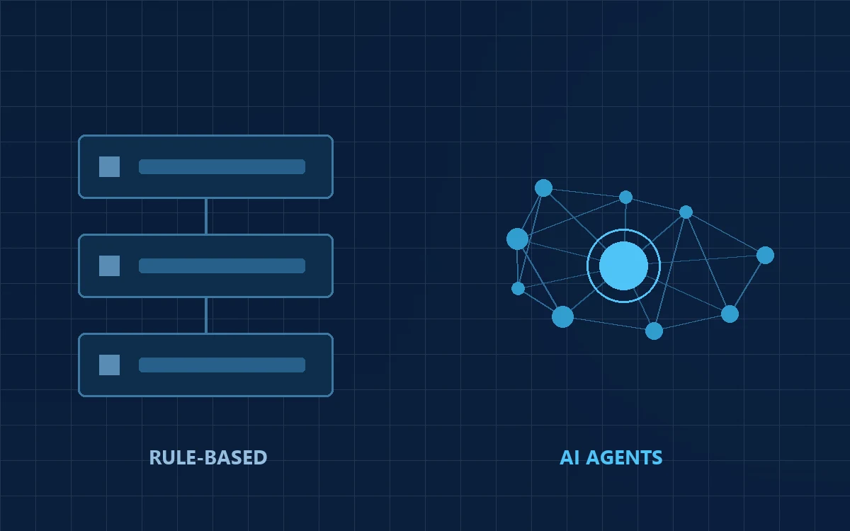
- Algorithm selection. Classical methods wherever they suffice; machine learning only where the defect resists rule-based description.
- Line validation. Testing against a reference set of good and defective parts under real production conditions, across shifts.
- Handover. Documentation, reference parts, verification procedure and operator training.
Conclusion
Computer vision is mature, well understood and delivers measurable returns on inspection, measurement, guidance and traceability. The technology is rarely the hard part.
What separates a working installation from a stalled one is upstream discipline: a defect defined numerically, lighting engineered so the defect is unmistakable, cycle time verified against the worst case, and a maintenance routine that catches drift before it reaches the line. Get the physical setup right and the software follows.